An electrical designer is creating an electrical equipment family which will host conduit that can be modeled from any point on a specific side of the equipment. How should this be accomplished?
How can an electrical designer see changes from other users without saving their own work to the central model?
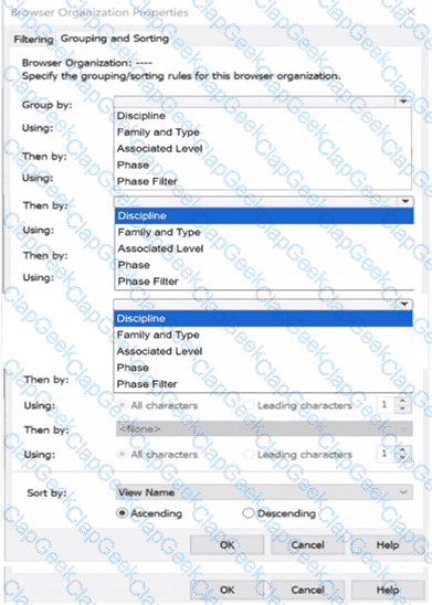
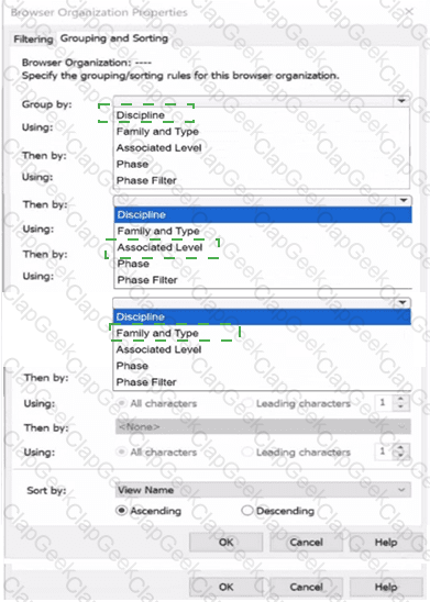
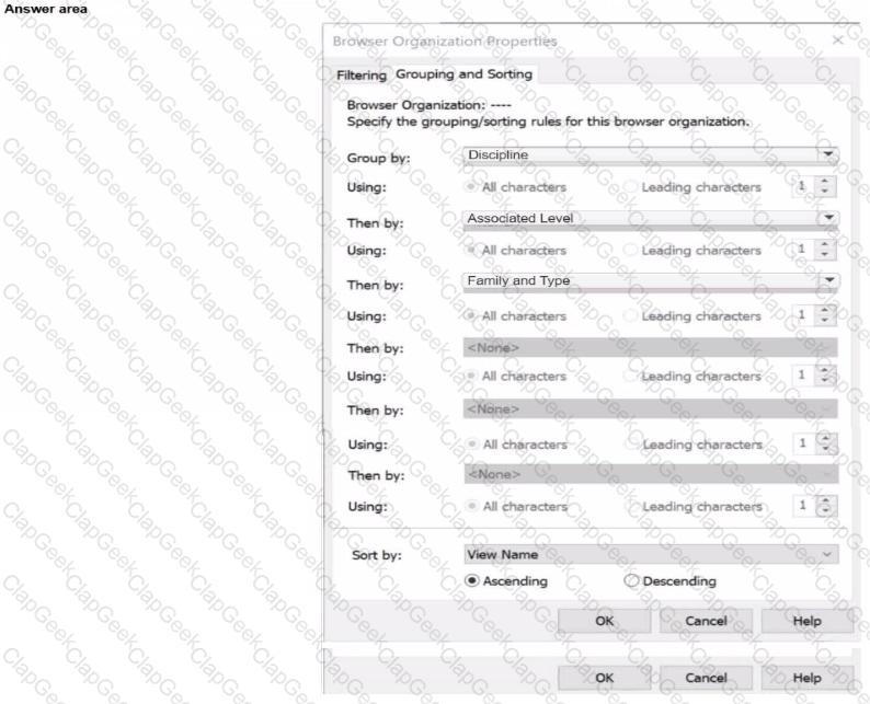
Refer to exhibit.
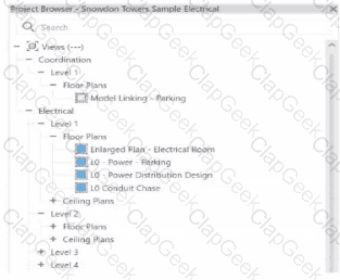
An electrical designer wants to organize the Protect Browser as shown in the exhibit. Select the correct options in order to achieve the desired organization. (Select three.)
Refer to exhibits.
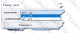
(The image Is presented in Imperial units: 1 In = 25 mm (Metric units rounded].)
An electrical designer creates a lighting fixture family with the following types and then saves the family.
An electrical designer needs to add spaces to a model displaying the architectural room name and number. What should the designer do before creating the spaces?
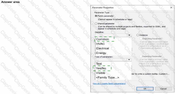
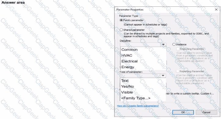
An electrical designer is creating a panelboard family. The electrical designer wants to create a family parameter to control the visibility of a clearance zone. In the Parameter Properties dialog, select the required Discipline and Type for the parameter.
Refer to exhibit.
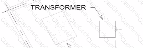
An electrical designer wants to place electrical equipment on the pad.
How should the component be aligned to the pad before placement?
Refer to exhibit.
A portion of an electrical fixture family's Type Properties is shown in the exhibit.
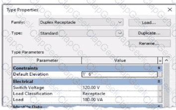
Because of the value of the Type Parameter Load Classification, an electrical designer expects the fixture's Load Classification to display as -Receptacle" when circuited. Instead, it displays as "Other".
What should the designer do to make the circuited fixture's Load Classification always match the family's Type Parameter?
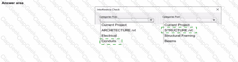
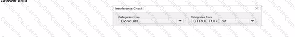
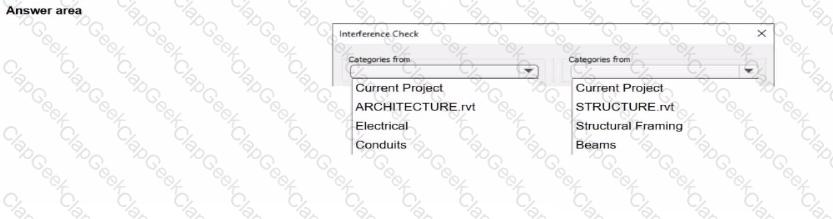
An electrical designer needs to check for Interferences between conduit in the host model and beams in a linked structure model in the Interference Check dialog, select the items that the designer must select to perform the interference check. (Select two.)
Refer to exhibit.
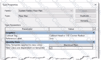
An electrical designer is reviewing the Type Properties for a floor plan view. How will the view behove when creating a new floor plan?
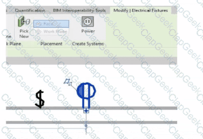
Refer to exhibit.
(The Image is presented in Imperial units: 1 In = 25 mm [Metric units rounded).)
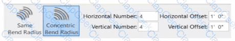
What is the electrical designer trying to do as shown in the exhibit?
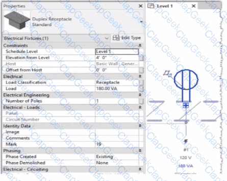
Refer to exhibit.
An electrical designer is circuiting a dwelling unit. The receptacle (electrical fixture) shown must be controlled by the switch (lighting device) shown to switch a plug-in lamp When the receptacle is selected, Revit does not provide an option to add the receptacle to a switch system.
What is causing this issue?
Refer to exhibit.
(The image is presented in Imperial units: 1 In = 25 mm [Metric units rounded].)
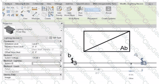
An electrical designer is trying to add the selected three-way switch to the existing switch system "b". The designer is unable to add the switch to the switch system.
Why is this problem occurring?
Refer to exhibits.
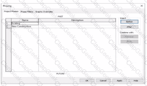
An electrical designer models an existing receptacle on an existing wall that the architect has indicated to be demolished.
The view is intended to show demolition, and the view's Phase is set to New Construction. How should the designer indicate that the receptacle must also be demolished?
An electrical designer wants to schedule parameters from generic annotations Which type of schedule must be created?


TESTED 06 Jul 2026
 C:\Users\Waqas Shahid\Desktop\Mudassir\Untitled.jpg